
Review the characteristics and components of cascading and pilot street light systems.
- Review the major components of a street light luminaire.
- Wire the dual voltage ballasts on the street light board for both 120- and 240-V operation.
- Perform and record operating voltages for both the 120- and 240-V ballast connections.
- You will discuss and note the hazards of a street light system and safety precautions to take during maintenance.
There are two types of supply systems used in roadway lighting --series and multiple or parallel. We will focus on the multiple system.
Usually a number of components make up the total street lighting system. A typical individual light installation is comprised of a
pole, a bracket which often holds the light fixtures some distance away from the pole closer to the road, a luminaire (which is the name applied to the fixture), a lamp, a supply of power and a method of control.
The lamps in a multiple connected roadway lighting system are, as the name suggest, connected in parallel or multiple. The lamps
are usually connected in small groups, as compared to the large number of lamps that can be connected in a series circuit. The size of group in a multiple system is dependent upon the number and wattage of the units, the size of the conductors required, and the voltage regulation in the circuit.
Alternatively to grouping the lamps, they may be connected directly to the existing secondary circuits and controlled individually.
The voltages commonly used in the multiple circuits are 120/240 V single phases. Under certain circumstances, mostly for special projects, 120/208 V or 347/600 V systems are used.
There are basic methods of laying out a multiple connected roadway lighting system as follows:
a) Use existing secondaries with individual lamp controls.
b) Use existing secondaries with group control.
c) Use separate secondaries and separate transformers with primary control.
While other methods may be available they are, for the most part, variations or combinations of the three methods previously mentioned. A description of the basic methods is as follows: where secondary circuits exist, the lamps may be directly connected to them and each lamp controlled individually. The individually controlled lamp system has merit especially in areas where lamp spacing is excessive and where control circuits are not available. The governing factor in the individually controlled system is usually the cost when comparing the additional equipment needed in a group system as against that required in the individually controlled system.
The somewhat sporadic operation of the lights, caused by the inequalities of the photo cells used, need not be objectionable if the photo controllers are set to operate while the level of the incident light is still reasonably high.
In industrial areas problems may arise with individually controlled lamps where dirt accumulation on the photo controller can cause false operation. If the accumulation is severe enough it can completely shield the cell and the lights would remain on continuously.
Where secondaries exist and individual control is not desired it is possible to group the lamps into sections. Each section will require a separate relay. All relays can be centrally controlled using a control or pilot wire or cascaded.
Using Separate Secondaries and Separate Transformers with Primary Control
A complete system may be installed solely for the purpose of supplying the street lighting. In this system, a standard distribution transformer, sized in accordance with the lighting load, is used to supply only the street lighting circuit.
There are two methods of control used on this of system.
The primary of the transformer is connected through a controlled switch, usually an oil switch, to the primary supply. The secondary circuit to which the streetlight is connected is then connected directly to the transformer secondaries.
The second method is where the secondary is connected to the transformer through a controlled low voltage relay and the transformer primary is directly connected to the primary supply.
The separate secondary type of system has some advantages in that it releases residential distribution transformer capacity for its intended use. Secondary system faults can be restricted to small areas so that large blocks of lights are not affected as can happen with other systems.
Disadvantages include the fact that the lighting transformers are idle for long periods of time.
The system with which a street lighting system is controlled consists of the initial control device or devices and an intermediate control system if required.
The initial control devices will be one of the following:
a) Manual control switch
b) Photo-electric controller
c) Time clock.
The intermediate control systems will be one of the following:
a) Pilot wire (low voltage)
b) A series of cascading relays
c) Carrier control either wire or wireless.
All street lighting systems are controlled by either one or a combination of more than one of the aforementioned systems.
One method of controlling several multiple street lighting circuits fed by different transformers is by a pilot wire and multiple relays. This system of street light control can have the pilot wire isolated at night, Figure 1, or the pilot wire energized, Figure 2.
Pilot Circuit De-energized at Night
Figure 1

Pilot Circuit Energized at Night
Figure 2
The relays that operate on a pilot system are referred to as
Normally Open or Normally Closed relays.
The term "normally open" or "normally closed" relay refers to the position of the contacts on the 120 V switch, when there is no current flowing through the control coil.
Therefore the normally open relays will need a pilot wire which is energized at nightfall to allow the contacts to close. In like manner the normally closed relays will need a pilot wire energized during the daylight hours to hold the contacts open.
The advantage of the later method of street lighting is that if any defects occur in the system during the day, the lights will go on, the defect will be detected and repairs can be made during the daytime.
Another method of using relays to control several lighting circuits is the cascading method. In this method it is not necessary to run a separate pilot wire. The first circuit, upon being energized, activates a relay, which energizes a second circuit; a relay, activated by the second circuit, energizes a third circuit, and so forth (Figure 3).
Method of Cascading Multiple Circuits
Figure 3

A disadvantage of the cascading system is that in case of relay trouble, all subsequent circuits of the controlled group of circuits will be affected.
In a pilot wire circuit, relay trouble is confined to the circuit it controls, and all other relays will continue to operate, except of course, the control relay for the pilot wire itself.
The extensive use of street lighting has made remote controls necessary d e relatively inexpensive and dependable modern automatic control devices have replaced manual controls in most instances.
There are three types of light-sensitive cells used in photoelectric controllers.
a) Photo-tube
b) Self-generating photovoltaic cell (barrier layer type)
c) Cadmium sulphide (CdS) photoconductive cell.
The controller using the CdS photocell is inexpensive and is available in a range of capacities for use on systems ranging from 120 to 277 V. It is usually rated in both wattage and in volt amperes for use on incandescent lamp systems and in volt amperes for use on systems with inductive-type loads. This type of photo controller is rugged and may be equipped with a fail-safe feature that ensures the lamps remain operating, in the event of most component failures.
The location of the photoconductive cell is important. The cell should have a clear view of the northern sky, free from shadows of tall buildings, trees, or the pole on which it is mounted. It should also be installed in a location away from a fixed source of artificial lights or transient lights, which can cause false operations.
The time clock control consists of an astronomical dial clock driven by a synchronous motor. The clock then adjusts the time of the contact operation in accordance with seasonal variations of daylight and darkness.
The one major disadvantage of a time clock control is that outages on the electric supply will cause the clock to stop and thus the street lighting system will be off schedule. However, the situation can be remedied by the use of an electrically wound spring driven clock which operates for up to a period of twenty-four hours when the supply is off.
The control of street lighting systems by carrier control or radio control provides a synchronized lighting system in which all of the groups of lights in a multiple system or several series systems can be operated simultaneously.
The carrier control system is frequently used to control intermediate relays. The system basically consists of a signal generator from a central location which, when operated, imposes its signal on the system which causes frequency sensitive relays to operate and provide the necessary control of the street lighting system.
An effective street lighting system calls for street and/or roadway illumination as darkness approaches that may be shut off as daylight returns.
In the past this was done by manual operation of switching devices that required some member of the operating utility be given this specific task.
Photo-electric type controllers designed for street lighting applications may used for the individual control of a single street lighting luminaire, for the control of several luminaires connected to a secondary cable, or for the control of many luminaires through suitable relays connected to a control wire and photo-cell.
Sitting of the photocell control unit is important. The window must face as near north as possible. Locations close to trees, wooded areas or tall buildings should be avoided so that shadows or reflections do not effect the normal sensing of daylight levels.
Photoelectric controllers used in street lighting services generally are the normally closed (NC) type made to "fail safe". Should there be a component failure other than in the photocell relay itself, the relay closes, energizing the street lighting circuits. Street lights that are on in the day-time usually indicate either control trouble or work being done on the street lighting system.
The photoelectric control operates when natural illumination falls below or rises above a certain level.
The control contains a relay coil, photocell, series resistor,
lightning arrester, and line, load and common terminals.
It operates by allowing alternating current to flow from the line terminal, through the relay coil, photocell and the series resistor to the common terminal. The current flow through the relay coil is controlled by the photocell resistance, which varies inversely to the light intensity on the photocell. As the light level drops to a desired foot-candle setting, the current flow is lowered to the point where the relay armature is released, and the load contacts close.
In the same manner, as daylight approaches, the amount of light shining on the photocell causes a current to flow, which opens the relay contacts, causing the street lights to go out.
A time delay feature of 30-60 seconds in some photoelectric cells, prevents false switching due to temporary cloud movements, momentary flashes of lightning or car headlights.
This type of control can control several circuits at once or can be mounted individually on every light.
A modern photoelectric controller, which is capable of 1000 W load, is so designed that if a component of the photocell fails, the load circuit will remain energized.
Photocells come in different voltage ranges
Gray - l2OV
Red - 208-240V
Green - 347 V
Blue - 240 V
Another timing device is an astronomical time control, or clock.
Through a complex set of gears and moveable cogs, it adjusts the "on" and "off" times to conform to seasonal changes in the hours of darkness. At the predetermined times, the clock opens and closes contacts to control another circuit.
A multiple relay switches one or both hot legs of a distribution transformer secondary that supplies power to several street lights that are connected in parallel. There are several types of multiple relays. Each is remotely controlled and responds electro-magnetically to open or close a set of contacts.
The single-pole multiple relay is designed to open and close one leg of a distribution transformer, and it is called a single-pole relay because it switches only one wire. The relay in this example has a coil, an armature, a spring, a set of contacts, a 60-A fuse, and a lightning arrester.
When the relay coil is energized, the armature is drawn to it. This action closes the contacts and energizes the streetlights. When the coil is de-energized, the contacts open, and the streetlights are deenergized. The fuse protects the distribution transformer from fault current on the circuit, and the lightning arrester protects the relay control coil.
The relay is a double-pole relay with a self-contained socket assembly. A double-pole relay works much like a single-pole relay, but it is designed to switch both hot legs of a three-wire service.
1. Name the two basic electrical circuit configurations for street lighting circuits.
a)
b)
2. In a parallel circuit, the voltage measured at each load remains constant when additional loads are added to the circuit.
TRUE FALSE
3. Adding a load to a series circuit decreases the total current flow through the circuit.
TRUE FALSE
4. A ________________________________ keeps current in a circuit at a constant value by adjusting voltage according to the varying resistance, or resistances, of the connected load.
5. Which of the following components could be found in a typical multiple street lighting system?
a) Primary oil switch
b) Astronomical time control (clock)
c) Photoelectric control
d) All of the above
e) Only a and c
1. Circle the correct answer.
The component in a basic circuit that opens and closes the path for current is called a
a. Source
b. Path
c. Load
d. Control
2. Circle the correct answer.
Street lighting controls can be operated from
_________________ of a distribution transformer.
a) Only the primary side
b) Only the secondary side
c) Both the primary and secondary sides
d) None of the above.
3. Circle the correct answer.
Which of the following is NOT a type of secondary control device?
a) Photo cell
b) Primary oil switch
c) Multiple relays
d) Bi-metal photoelectric cell
TRUE FALSE
TRUE FALSE
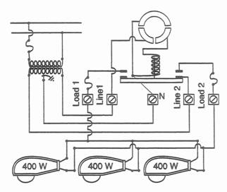
Using the following diagram answer questions 6-8.

6. What is the controlling device for the circuit, and how is it activated?
______________________________________________________________________________________________________
7. Which of the following are correct statements about the circuit? Circle the correct answer.
a) The source for the photocell circuit is the 120 V from the secondary main.
b) The primary oil switch control coil is the load of one circuit, and the switch's relays are the control for another circuit.
c) The circuit for which the ballast transformers are loads having no separate controlling device.
d) All of the above.
e) Only a and b
8. The mercury vapor lamps are loads in three circuits, although more of the circuits have a separate control device.
TRUE FALSE
Using the following diagram answer questions 9 and 10.
9. What is the function of a double-pole multiple relay, and how is the relay activated?
_________________________________________________
_________________________________________________
10. The source and path to the photocell circuit are also the source and path to the control coil of the multiple relay.
TRUE FALSE
LUMINAIRES:
A luminaire is a self-contained weatherproof lighting unit that houses a ballast transformer, bulbs, and related circuitry. The luminaire shown in Figure 4 is completely enclosed, and it contains a ballast transformer, a lamp, and a photocell socket assembly.
Luminaire
Figure 4

The transformer in a typical luminaire is rated at 120/240 V. Most
luminaires also contain large capacitors, which help strike the arc in a mercury vapor or sodium vapor lamp. Luminair head comes in different wattage approximately the same size head.
125 W Medium Base
125 W Mogal Base
175 W Mogal Base
250 W Mogal Base
400 W Mogal Base
1000 W Mogal Base
50 W Mogal Base
70 W Mogal Base
100 W Mogal Base
150 W Mogal Base
250 W Mogal Base
400 W Mogal Base
Luminaires were designed to be used wherever building a multiple
circuit was not possible or practical. A luminaire can be connected to standard residential mains wherever lighting is needed.
A luminaire can also be connected to an existing multiple circuit with the proper voltage rating. When this is done, the photocell is usually bypassed so that all of the lamps on the circuit can be controlled from one location.
Luminaires can be categorized as either horizontal burning or vertical burning. Vertical burning units, are generally used to light individual customer properties and are sometimes referred to as dusk-to-dawn lights or security lights.
Horizontal burning luminaires are generally used for street lighting. This type of luminaire usually has a hinged door that houses the lamp refractor. A refractor is a transparent material, generally either glass or plastic, that bends the lamp's light rays in the desired direction. The hinged door unlatches to expose the lamps and reflector, the ballast transformer, the photo control wiring, and other circuit wiring.
Some have two doors. One door, the refractor, opens to expose only the lamp, socket and reflector, d e other door opens to expose the ballast and other electrical circuitry.
As previously noted, the luminaire provides control of the light so that the street is illuminated in the desired way. Even though a number of luminaires may look the same, very different light patterns can be achieved by adjusting the relative positions of the refractor, reflector and lamp. Do not make adjustments without being aware of the effect.
Manufacturers of Luminaires have listings of various Light
Distribution patterns obtained by changing the socket position. The socket has five adjustment positions if the light is required mostly on the road. The socket can be moved to the rear of housing if the light is required on the sidewalk, the socket can be moved to the front of the housing, to change the concentration of light. There are five settings - A, B, C, D, E. Most luminaires are on C for an even flow of light.
In addition, even if the pattern of light emerging from a number of luminaires is identical, very different street lighting results will be achieved if the luminaires are tilted or otherwise misaligned.
The streetlight designer uses graphs and charts to determine what type of light pattern will work best on the particular street in question. However, all of the calculations are based on a luminaire which is mounted level and at right angles to the road center line. Usually it is not too difficult to adjust the luminaire at right angles by "eye-balling" it. However, getting it level is a different matter and to assist, the manufacturer will provide either a leveling pad or a leveling surface on which a carpenter's level can be used. On most cobra head luminaires this surface is on top of the unit near the bracket attachment point. Leveling is achieved by slackening off the adjustment bolts at the slip-fitter assembly, which holds the luminaire on the bracket. The luminaire is then held in place by hand while the bolts are retightened. After tightening is complete, re-check for level in all directions.
In special cases where lighting is on only one side of a wide roadway, the luminaire can be tilted (or "pitched") upward to cast more light to the far side. It is preferable to redesign the lighting in a case like this to take advantage of alternate socket settings, refractors and mounting heights, which are available. Luminaires may also be slightly "rolled" on the bracket to improve the light distribution pattern where steep hills are encountered.
The following diagram (Figure 5) illustrates some of the various types of distribution patterns which are available by selecting some of the above options.
Figure 5

The inside of the luminaire is warm and dry and therefore is an attractive place for a bird to build a nest. There are two main problems which arise when birds inhabit a luminaire - the nesting materials prevent normal air circulation and can result in ballast failure due to overheating and also disturbed birds may fly out into the faces of maintenance personnel startling them and creating a dangerous situation. Luminaire manufacturers recognize the bird problem and provide "bird stops" which are inserted around the bracket slip-fitter to prevent our feathered friends from entering.
Luminaires come from the manufacturer prewired and ready to install. The only electrical connections that must be made are those from the power supply wiring at the pole. The system ground wire should be connected to the ground lug on the luminaire. Then the system neutral and line conductors may be connected at the terminal block. Refer to the wiring diagram for information specific to a particular manufacturer. After completing the electrical connections, a test should be conducted to ensure the luminaire will operate. Don't forget to install a photo electric controller (PEC) in the twist-lock socket if PEC control is specified. In an actual installation in the field it is important to loosen the screw on the PEC socket and rotate the socket until the PEC window or arrow faces north for it to perform correctly.
The reflector, which is housed over the lamp, is also adjustable. It is slotted so that the reflector can be adjusted up or down. When it is in the up position it allows more circulation of light. When in the lower position there is a concentration of light in one direction.
Most luminaire reflectors are in the center position for an even flow of light.
The refractor is a corrugated glass or plastic which is fastened to the door. Its purpose is to spread the light over both the road and sidewalk. If there were just plain glass or no glass at all the light would be just a spot on the road.
To provide the required illumination level and uniformity level, the mounting height and spacing of luminaires assumes considerable importance. The mounting height should be fixed for a particular luminaire in a street lighting installation since it is a factor in controlling glare. The spacing of Iuminaires is a variable depending on existing pole locations or desirable new locations.
MINIMUM RECOMMENDED LUMINAIRE MOUNTI>NG
HEIGHTS
The following table provides an indication of recommended minimum mounting heights:
Lumens Recommended Minimum
Mounting Height (ft)
up to 6,000 25
6,000-18,000 30
18,000-26,000 35
greater than 26,000 40+
a) Incandescent (INC)
b) High Intensity Discharge Lamps
1. Mercury vapor (MV)
2. Metal halide (MH)
3. Low pressure sodium vapor (LPS)
4. High pressure sodium vapor (HPS)
5. Fluorescent (FL)
(a) Incandescent LampsAn incandescent street lamp is similar to the light bulbs used in the home. These lamps generate light by heating a piece of wire or filament to a temperature that is high enough to produce light. The heat is generated by passing a current through the lamp.
The filament of an incandescent lamp is usually made of tungsten.
Tungsten is a metal that retains much of its physical strength even at very high temperatures. The filament is sealed in an oxygen-free glass container, or bulb. The absence of oxygen helps prevent the filament from burning up.
The incandescent lamps used in multiple street lighting systems are rated in terms of voltage, watts, and lumens. The supply voltage to each lamp in a multiple circuit is the same. For incandescent lamps, the supply voltage is usually 120 volts. Wattage is equal to current times voltage. Therefore, if the current flowing through a lamp is 2 amps and the lamp is energized at 120 volts, the wattage is 240 watts:
Current x Voltage = Wattage
2 amps x 120 volts = 240 watts
When a light is burning, energy is radiated from it in much the same way that heat is radiated from a radiator. The energy radiated from a burning light includes heat, visible rays, and invisible rays. The part of energy that produces what is perceived as light is called light energy, or luminous energy. The luminous energy, or light output, of a lamp is given in units called lumens. The higher a lamp's lumen rating, the higher its light output.
(b) Gaseous Discharge Lamps
Gaseous discharge lamps have gradually become more common than incandescent lamps because they produce more lumens per watt. In other words, a gaseous discharge lamp is more efficient:
It produces more light for less money. Two of the most common types of gaseous discharge lamps are mercury vapor lamps and sodium vapor lamps.
1. Mercury Vapor Lamps
The inside of a mercury vapor lamp consist of an enclosed glass or quartz arc tube that contains argon gas and a small amount of liquid mercury. An electrode is sealed in each end of the arc tube. These electrodes are called the main electrodes. In one end of the tube, next to the main electrode, is a starting electrode. The starting electrode provides the initial glow that is needed to start the lamp. The starting electrode is connected in series with a resistor.
To start the lamp, the starting electrode provides a small glow discharge in the argon gas. As with any circuit, current flow is along the path of least resistance. Initially, the path of least resistance is between one of the main electrodes and the starting electrode.
The heat produced by the glow discharge vaporizes some of the mercury, which, in turn, increases the internal pressure in the tube and causes an arc to strike between the main electrodes. Between 200 and 350 volts is required to strike the arc in a watt mercury vapor lamp. The way that this voltage is generated is discussed in Section on Ballasts.
Once the main arc has been struck, the starting electrode becomes inactive, because it is connected in series with a resistor. After the main arc is struck, the path of least resistance is between the two main electrodes.
The average 400-watt mercury vapor lamp has an output of approximately 50 lumens per watt and a life expectancy of 24,000 burning hours. If this type of lamp burns for an average of 12 hours a day, it should last almost 5-1/2 years.
By comparison, the average incandescent lamp, which has a lumens-per-watt rating of approximately 17 and a life expectancy of 3,000 burning hours, it should last less than a year.
2. Sodium Vapor Lamps
Sodium vapor lamps are even more efficient than mercury vapor lamps. This type of lamp first came into use in the 1930's when low-pressure sodium (LPS) lamps were introduced.
An LPS lamp has a lumens-to-watt efficiency that is more than three times that of a mercury vapor lamp. However, an LPS lamp has some disadvantages. For example, the LPS lamp has a poor color, and it has an extremely long arc tube, which requires a fixture that is quite large. For these reasons, the LPS lamp has been very poorly accepted in the United States .
In the early 1960's, new materials were developed that allowed sodium vapor lamps to be made smaller and to operate at higher pressures. These new materials allowed the low-pressure lamp to evolve into the high-pressure sodium (HPS) lamp.
The average HPS lamp has a 100 lumens-per-watt rating, and about a 20,000 hour life expectancy. This is less lumens per watt than the LPS lamp, but still twice that of a mercury vapor lamp. The average HPS lamp can last approximately 4-1/2 years.
The HPS arc tube is a slender cylinder that is approximately 3/8 of an inch thick. Because of the arc tube's small diameter, however, it is difficult to place a starting electrode close enough to spark a main electrode and start the lamp. As a result, the lamp requires a high supply voltage to compensate for the missing starter and to supply the arc needed to start the lamp. The typical voltage needed to start an HPS lamp is approximately 2500 volts, which is much higher than the starting voltage for a mercury lamp. After the lamp is started, the supply voltage drops to a lower operating level, just as it does for the mercury lamp.
1. List the two basic types of lamps used in multiple street lighting systems.
a)
b)
2. __________________________ is the energy radiated from a burning lamp that is perceived as light.
3. An incandescent lamp is much more efficient than most
gaseous discharge lamps.
TRUE FALSE
4. In a mercury vapor lamp, the path of least resistance is between the main electrode and the (a)___________________________ before the arc is struck, and between (b) ________________ after the arc is struck.
5. The average lamp has a 100 lumens-per-watt rating and a life expectancy of about 4 1/2 years. Choose one.
a) Incandescent
b) LPS
c) HPS
d) Mercury Vapor
A ballast transformer is an auxiliary device that limits current flow and provides the proper starting and operating voltages for a gaseous discharge lamp. Although ballast transformers are available in a variety of styles, they all perform this same basic function.
In gas discharge type lamps such as mercury vapor and fluorescent lamps, the resistance of the current path is not fixed as the path is in a vacuum tube. Therefore, as the increasing current passes through the vacuum tube, the resistance of the path decreases, and unless this process is restrained by some means, it will continue to build up until so much current is carried the lamp will burn out.
In an incandescent lamp the resistance to the current flow is a fixed factor due to the filament itself and therefore does not require a ballast.
The way a ballast transformer produces the required voltages in a multiple street lighting circuit depends on the type of gaseous discharge lamps in the circuit. Mercury vapor lamps and high-pressure sodium vapor lamps have different voltage requirements.
Types of Ballasts. See Figure 6 and 7 for Typical Wiring Diagrams as provided by Manufacturers.
Figure 6
Wiring Connection at Terminal Block
for 120 V & 120/240 V Luminaires

Standard 50 -150W -120V HPS Luminaire Wiring Diagram
A ballast transformer may be connected in different ways to various light sources. In a low-voltage connection the primary coils are connected in parallel (see Diagram A).
A higher voltage connection in the primary coils are connected in series (See Diagram B).
Diagram A
Shows the interconnecting wiring
for ballasts tapped for 120V or 240 V operation

Diagram B
Shows wiring for a 120V only ballast connection
Figure 7

As stated earlier, between 200 and 350 V is needed to strike the initial arc in 400 W mercury vapor lamp. Drastically the arc is struck, the internal resistance in the lamp drastically decreases. To keep the resulting high current flow from destroying the lamp, the voltage to the lamp must also decrease.
To provide the proper voltages, ballast transformers make use of capacitive discharge and the high inductive reactance of the transformer's secondary coil. The coil acts in series with the internal resistance of the lamp.
High pressure sodium ballasts have a starting aid in the form of an electronic solid state circuit which provides superimposed pulses of 25000 or 4000Volts + during starting. This is in addition to the normal magnetic circuit that controls the open circuit voltage and limits the lamp current. A full range of lead or lag ballasts are available, giving a high power factor of 90% plus or a low power factor of 50%. Because of the relatively high voltage starting characteristics of these ballasts, the life span may be reduced when they are left connected to a defective or burnt out lamp over an extended period of time. It is also extremely dangerous to attempt to change lamps while the electrical circuit and ballast are alive.
The starting aid, combined with a capacitor and a ballast transformer, provides the starting voltage and the operating voltage for the HPS lamp. When the energy reaches a sufficient level, the starting aid discharges it into a few turns of the ballast transformer windings. The ballast acts like a booster transformer. It steps up the pulse from the starting aid to the required voltage level.
NOTE:
In both cases of low and high pressure sodium ballasts the supply voltage will effect the color output of the lamp if it is not held within the recommended tolerance, i.e., HPS will appear rather pink and the LPS will appear to be orange.
1. What is the function of a ballast transformer?
________________________________________________
________________________________________________
2. A ballast transformer may only be connected in circuits in which the primary coils are connected in parallel.
TRUE FALSE
3. A mercury vapor lamp at room temperature requires a higher strike voltage than the same lamp at a higher temperature.
TRUE FALSE
4. Because the starting voltage for an HPS lamp is greater than
that for a mercury vapor lamp, ballast transformers used with
HPS lamps require an electronic_____________________.
5. A self-contained lighting unit that includes a ballast transformer, bulbs, and related circuitry is called a
________________________.
High pressure sodium ballast circuits contain high voltage electronic pulse generators which supply 2500- 4000 V pulses to the lamp for starting. The high voltage starting pulse may bold a charge at any time. One should wait at least 30 seconds after the power has been disconnected before proceeding with any checks on the high pressure sodium lamp. A quick way to de-energize the circuit would be by shorting the two contacts on the capacitor.
In a delta system, an ungrounded luminaire could become energized with phase voltage. All ballasts must be isolated so the luminaire cannot be energized. Grounding of luminaires should be in accordance with your utility's guidelines. The standard method for grounding a street light luminaire is by connecting a multi-grounded system neutral to the grounding lug of the luminaire casing. The neutral may be a primary, secondary or common neutral, provided it is multi-grounded by interconnections with equipment and service grounds and there is a continuous connection to the secondary neutral of the transformer supplying the lighting load. Where a neutral is not available, ground rod(s) shall be installed near the base of the pole and the luminaire ground conductor connected to it.
The quick isolation of circuits and luminaires to facilitate maintenance is desirable.
Individual fusing of streetlights, especially in underground supplied lighting systems is recommended. Quick disconnect weatherproof of submersible fuse holders are readily available.
Some of the materials used in street lighting equipment are considered hazardous and their disposal should be carried out in a safe way. The following techniques are recommended.
Lamp materials which require disposal include: glass; parts made of plastic; parts made of metals such as aluminum, brass, molybdenum; wires of copper and nickel plated iron; phosphors and other compounds which include mercury, sodium, antimony, iodine, thallium, scandium, thorium and cadmium.
At one time it was considered expedient to break inoperable lamps to reduce their bulk before final disposal. However, safety considerations now favor leaving lamps unbroken. This eliminates the danger of injury by cuts from glass and metals parts and by inhalation of fine glass particles, phosphors, mercury and other materials.
In addition, the danger of contamination of the landfill site by mercury and other chemicals is greatly reduced because they usually remain sealed hermetically inside the arc tube.
The recommended technique for lamp disposal, therefore, is to retain them unbroken in their protective envelopes and discard them in this state with the regular garbage.
It is possible for the outer bulb to be broken and the inner arc tube to remain lit, emitting ultraviolet radiation without the outer glass bulb to act as a filter.
Exposure to ultraviolet radiation, for even short durations, will cause burning of the eye tissue similar to sunburn or welding arc burns.
There may be no immediate sensation, but the eyes may become painful six to eight hours after exposure. Damage is usually temporary, but immediate medical attention should be obtained.
In addition, the phosphor coating of the outer bulb may be injurious if inhaled, ingested, or allowed to come in contact with the eyes, or any open wound.
PRECAUTIONS WHEN CHANGING BROKEN MERCURY VAPOR LAMPS
Before changing mercury or fluorescent lamps, which are broken or suspected of being broken, the circuit shall be isolated wherever practical and the defective lamp allowed to cool. Suitable face and band protection should be worn while replacing defective lamps. Where lamps must changed alive, flash goggles shall be worn.
Caution should be taken in the disposal of fluorescent lamps as they are a vacuum type glass and they will collapse violently when broken. Care should be taken that flying glass, phosphor powder or mercury fumes are guarded against.
Mercury relays contain a substantial amount of liquid mercury hermetically sealed in the switch tube. Although there is no danger to personnel handling these units, it is recommended they not be discarded in regular garbage. Instead it may be economically viable to sell the mercury switch intact to a scrap dealer who can recycle the mercury it contains.
CAPACITORS CONTAINING POL YCHLORINATED
BIPHENYLS (PCBs)
Until 1979, most of the capacitors used for power factor correction in street lighting luminaires contained PCBs and, therefore, handling and disposal of these capacitors must be in accordance with current regulations. Capacitors not containing PCBs will be clearly marked and unless so marked, all capacitors must be assumed to contain PCBs.
A facility for the destruction of PCBs will not be available for some time and a central authorized storage area is also not available. Therefore, until these facilities are available, each utility must retain this material in a clearly marked steel drum and store it in a secure area with appropriate precaution against leakage of other undesirable events.
DANGERS OF TROUBLESHOOTING AN ENERGIZED
HIGH PRESSURE SODIUM LUMINAIRE
High pressure sodium lamps installed in incompatible equipment could shatter, causing personal injury and damage to equipment
and property. Do not remove or insert the lamp when the power is on. In the event of a broken outer bulb, shut off the power immediately and remove the lamp to prevent exposure to ultraviolet energy, which can be harmful to eyes and skin. The outer bulb is vacuum jacketed and may implode if broken. Do not scratch glass or subject lamp to undue pressure as either may cause breakage or shattering. Suitable face and hand protection should be worn while replacing defective lamps.
CAPACITOR SPACING AND OVERCHARGED
CAPACITORS
The oil in present capacitors will support combustion and the capacitor case could rupture under a failed condition. Capacitors are presently constructed with an AFC rating (available fault current) and contain a pressure-sensitive disconnect to interrupt the circuit, to prevent the protective case from rupturing.
Pressure build-up in capacitors is caused by gassing of the internal materials, which results from massive dielectric faults, occurring at the end of the capacitors life. A pressure-disconnect panel is used to separate the internal tabs from the terminal rivet as the cover bulges. In its normal operation, the panel is flat and the internal tabs are connected to the rivet through the panel. If the cover bulges because of pressure build-up, the panel remains flat and the five move upward through the panel, shipping the tabs off the ends of e rivet. The electrical connection is broken and the capacitor ceases to operate (refer to Figure 4).
There must be at least a one-half inch space at the top of a capacitor having this type of AFC protection to permit the unrestricted operation of the disconnect. When converting from mercury vapor or metal halide to high pressure sodium, a slightly larger space for the capacitor should be provided to allow for expansion room at the terminal end of the capacitor.
LAMP
Mercury lamps are constructed with two bulbs, an inner bulb or arc tube and an outer bulb. The inner bulb contains the arc, while the outer bulb shields the arc tube from changes in temperature.
It is possible for the outer bulb to be broken and the inner arc tube to continue to emit ultra-violet radiation without the outer glass bulb to act as a filter. Exposure to ultra-violet radiation, for even a short duration will cause burning of the eye tissue similar to a sunburn or a welding-arc bum.
When changing a broken or defective lamp, the circuit should be
de-energized and the lamp allowed to cool. Protective goggles and leather gloves shall be worn while replacing the lamp.
Medical attention should be obtained if there is exposure to ultraviolet radiation, even for a short duration.
Take a few moments to examine the Ballast, Capacitor and Starter (if High Pressure Sodium) and the associated wiring. From the circuit diagram provided by the Manufacturer, trace all wires to confirm the actual luminaire is wired as specified from the factory diagram.
Wire up a typical luminaire ballast compartment so that it conforms. Have all wiring checked for correctness.
Wire up a suitable ballast for 120 V and then for 240 V operation as shown on the manufacturer's package slip.
Check the laminations in the ballast for looseness. Tighten the
bolts holding the laminations together if they are loose. In most
cases you will find that the laminations are welded together by the
manufacturer.
Note: Use caution when working around energized components.
You will wire up the ballasts and lights that are already mounted on the street light board. Be sure power is disconnected when making all connections.
Voltage Checks
With the lamp operating at normal brilliance, measure and record the following voltages: at line side (input) ballast terminals, on load side ballast terminals, across the lamp terminals.
Current Checks
With the lamp operating at normal brilliance, measure and record the following amperages: at the incoming line to the ballast, at the outgoing line from the ballast to the lamp.
Energize a luminaire and note how long it takes the output voltage and current of the ballast to stabilize. Record this time for various lamps and ballasts.
Note the effect of coveting over the photoelectric cell "window".
Note the time required for the luminaire to be shut-off when it is suddenly exposed to bright light triggering the photocell.
Utilize a photocell "shorting cap" to replace the photocontroller and energize a luminaire.
Utilize a photoceII to control two or more luminaires.
Utilize a photocell in conjunction with a relay to energize several
luminaires, note the time delay for the photocell to activate.
CAUTION:
Because of the high starting voltage pulse on the HPS lights you should wait approximately 30 seconds before doing the checks.
Disconnect the power to the lights while installing and removing all bulbs.
ANSWERS TO REVIEWS
REVIEW #1
1. a) parallel or multiple
b) series
2. TRUE
3. TRUE
4. constant current transformer
5. d) all of the above
1. d) control
2. c) both the primary and secondary sides
3. b) primary oil switch
4. FALSE
5. TRUE
6. The control is a primary oil switch, and it is activated by a photo cell.
7. d) all of the above
8. TRUE
9. The function of the relay is to control the Iuminaires by opening and closing the hot legs from the distribution
transformer secondary. The relay is activated by a photo
cell.
10. TRUE
REVIEW #3
1. a) Incandescent
b) Gaseous discharge or electric discharge
2. Light output
3. FALSE
4. (a) starting electrode
(b) two main electrodes
5. c) HPS
REVIEW #4
1. A ballast transformer limits current flow and provides the proper starting and operating voltages for a gaseous discharge lamp
2. FALSE
3. FALSE
4. starting aid
5. luminaire
This lesson will acquaint the learner with the major components of a Street Lighting System and provide basic information regarding luminaire installation, alignment and lamp data.
All intelligent undertakings have a purpose. Streetlighting is no exception in this regard and it is always wise to be clear about the purpose because it gives direction and dimensions to the undertaking. Some of the more important purposes of street lighting are as follows:
- cuts down on traffic accidents, both pedestrian and vehicular. This is a matter of record. Accidents are very costly in repair bills and medical expenses. They also cause lost hours from work and loss of wages in addition top~ suffering, anguish and great inconvenience
- prevents crime, Darkness invites crime. Acts are committed under cover of darkness, which would not be attempted otherwise for fear of detection. Police records provide the truth of this
- promotes business. A well-lighted commercial area will attract customers, which is the first step to good business. It is
the first line salesman
- promotes civic pride. Everyone likes to be identified and associated with good things
- stimulates community growth. Being the mark of a progressive community, lighting creates a good impression
on outsiders and invites businesses and residents to the area
There may have been a time when streetlighting was a luxury. Today, with fast moving traffic, crowded streets and a variety of equipment available to provide lighting, it is accepted as a necessity.
STREETLIGHTING SYSTEMS
Usually a number of components make up the total streetlighting system. A typical individual light installation is comprised of a pole, a bracket which often holds the light fixtures some distance away from the pole closer to the road, a luminaire (which is the name applied to the fixture), a lamp, a supply of power and a method of control.
Poles may be dedicated streetlight poles of various heights and materials or they may be electric power distribution, telephone, or traffic signal poles which are shared by streetlighting. Joint use poles help to reduce the total cost and reduce visual clutter. Streetlights in tunnels and underpasses are mounted on the walls or ceiling. In some instances, streetlighting is mounted on the face of the buildings, but this is not common.
Besides attaching the luminaire to the pole, brackets are used to extend the luminaire out from the pole towards the road and also to raise the luminaire.
The luminaire provides a weatherproof housing for the lamp and components such as the socket, ballast, starter and wiring necessary to make the lamp operate. In addition, the luminaire should provide the means to control the light by refraction and/or reflection to minimize glare and spread the light evenly in the area of the road where it is wanted.
The lamp is the actual light producing element and is supplied with electrical power through the socket in the luminaire housing. This power is obtained from the electrical system from either the secondary house circuit or from dedicated streetlight circuits. The light can be turned on and off with an individual photoelectric controller or as part of a complete streetlighting circuit switched by a relay and controlled by a photoelectric controller or timer.
Incandescent (INC) as illustrated in Figure 1, Mercury Vapor (MV) shown in Figure 3, High Pressure Sodium (HPS) as seen in Figure 5 and Low Pressure Sodium (LPS) drawn in Figure 6, are the most common sources although Fluorescent Figure 2 and Metal Halide Figure 4 are used sometimes. Incandescent lamps are the simplest. An electric current is passed through the filament, heating it white hot so it gives off light. All other lamps produce light because of an electric discharge through a gas. A ballast is used with these lamps to limit the current through the hot gas. All lamps are marked to indicate their type and wattage. Lamps which look the same can have a wide variety of wattages and because discharge lamps must be matched with a specific ballast, it is imperative to select the proper lamp. Streetlighting personnel should acquaint themselves with the designations used by the various manufacturers for marking the lamps. The Figures mentioned above illustrate some of the more popular types of lamps for streetlighting purposes.
Figure 1

Incandescent Lamp
Figure 2
Fluorescent Lamp
Figure 3

Mercury Vapor Lamp
Figure 4
Metal Halide Lamp
Figure 5

High Pressure Sodium Lamp
Figure 6
Low Pressure Sodium Lamp
The following lamps are recommended for streetlighting service:
INCANDESCENT: 150 W to 500 W Extended Service Lamps
(2500 hrs).
MERCURY VAPOUR:
Wattage ANSI Designation
125 W H42BF- 125DX
175 W H39KC- 175DX
250 W H37KC-2SODX
400 W H33GL-400DX
HIGH PRESSURE SODIUM
Wattage ANSI Designation
50W
70 W S62ME-70
100 W 554SB- 100
150 W S55SC- 150
200 W S66MN-200
250 W S5OVA-250
400 W S5 IWA-400
LOW PRESSURE SODIUM
Wattage ANSI Designation
35 W SOX-35
55 W SOx-55
90 W SOX-90
135 w SOX- 135
180 w SOX- 180
Lamp warranty is based on hours of burning or time in service and therefore it is necessary for the installer to mark the date on the lamp. See Table 1 for the current Rated Lamp Life (Hours)
The lamp manufacturer has facilitated this step by imprinting a date code on the lamp base. The year is indicated by the numbers 1234567890. To indicate a lamp installation date of March 1983, the installer marks the code as follows, either by scratching the base with a sharp tool or by using an indelible felt marker.
JFMAMJJASOND 1234567890
Lamps must be handled with caution. It is a good idea to wear gloves and avoid undue pressure on the glass. Do not allow the bulb to become scratched as this could increase the possibility of breaking. Avoid rough handling or dropping and retain the lamp in its protective corrugated cardboard shipping container for as long as possible while it is being handled. OBSERVE ANY MANUFACTURER'S WARNINGS ON THE PROTECTIVE CARTON, e.g., Caution re fingerprints on the envelope of the Quartz-Halogen Lamp.
TABLE 1
Street Lighting kW Load Guidelines

Some of the materials in Streetlighting Equipment are considered hazardous and their disposal should be carried out in a safe way. Lamp materials which require disposal include: glass; parts made of plastic; parts made of metals such as aluminum, brass, molybdenum; wires of copper and nickel-plated iron; phosphors and other compounds which include mercury, sodium, antimony, iodine, thallium, scandium, thorium and cadmium.
At one time it was considered expedient to break inoperable lamps to reduce their bulk before final disposal. However, safety considerations now favor leaving lamps unbroken. This eliminates the danger of injury by cuts from glass and metal parts and by inhalation of fine glass particles, phosphors, mercury and other materials. In addition, the danger of contamination of the landfill site by mercury and other chemicals is greatly reduced because they usually remain sealed hermetically inside the arc tube.
The recommended technique for Lamp Disposal is to retain them unbroken in their protective envelopes and discard them in this state with the regular garbage. Your utility may have a different policy for lamp discarding.
As previously noted, the luminaire provides control of the light so that the street is illuminated in the desired way. Even though a number of luminaires may look the same, very different light patterns can be achieved by adjusting the relative positions of the refractor, reflector and lamp. Do not make adjustments without being aware of the effect
Manufacturers of Luminaires have listings of various Light
Distribution Patterns obtained by changing the socket position. See
Table 2 for a sample listing of some typical Light Distribution
Patterns resulting from a variety of Socket Positions for commonly
used Luminaires.
In addition, even if the pattern of light emerging from a number of luminaires is identical, very different streetlighting results will be achieved if the luminaires are tilted or otherwise misaligned.
The streetlight designer uses graphs and charts to determine what type of light pattern will work best on the particular street in question. However, all of the calculations are based on a luminaire which is mounted level and at right angles to the road centre line. Usually it is not too difficult to adjust the luminaire at right angles by "eye-balling" it. However, getting it level is a different matter and to assist, the manufacturer will provide either a leveling pad or a levelling surface on which a carpenter's level can be used. On most cobra head luminaires this surface is on top of the unit near the bracket attachment point. Leveling is achieved by slackening off the adjustment bolts at the slip-fitter assembly which holds the luminaire on the bracket The luminaire is then held in place by hand while the bolts are retightened. After tightening is complete, re-check for level in all directions.
TABLE 2
Luminaire_Conversion_Chart

In special cases where lighting is on only one side of a wide roadway, the luminaire can be tilted (or "pitched") upward to cast more light to the far side. it is preferable to redesign the lighting in a case like this to take advantage of alternate socket settings, refractors and mounting heights which are available. Luminaires may also be slightly "rolled" on the bracket to improve the light distribution pattern where steep hills are encountered.
The following diagram illustrates some of the various types of distribution patterns which are available by selecting some of the above options.

The inside of a luminaire is warm and dry and therefore is an attractive place for a bird to build a nest There are two main problems which arise when birds inhabit a luminaire�the nesting materials prevent normal air circulation and can result in ballast failure due to overheating, and also, disturbed birds may fly out into the faces of maintenance personnel startling them and creating a dangerous situation. Luminaire manufacturers recognize the bird problem and provide "bird stops" which are inserted around the bracket slip-fitter to prevent our feathered friends from entering.
Luminaires come from the manufacturer prewired and ready to
install. The only electrical connections that must be made are those from the power supply wiring at the pole. The system ground wire should be connected to the ground lug on the luminaire. Then the system neutral and line conductors may be connected at the terminal block. Refer to the wiring diagram for information specific to a particular manufacturer. After completing the electrical connections, a test should be conducted to ensure the luminaire will operate. Don't forget to install a photoelectric controller (PEC) in the twist-lock socket if PEC control is specified. In an actual installation in the field it is important to loosen the screw on the PEC socket and rotate the socket until the PEC window or arrow faces north for it to perform correctly.
Two methods are in use to switch multiple lighting circuits fed from different secondaries or transformers on and off.
These are:
1, Pilot wire
2. Cascading
One method of controlling several multiple street lighting circuits fed by different transformers is by a pilot wire and multiple relays. This system of street light control can have the pilot wire isolated at night, Figure 7 or the pilot wire energized at night, Figure 8.
Figure 7
Pilot Circuit De-Energized at Night

Figure 8
Pilot Circuit Energized at Night
The relays that operate on a pilot system are referred to as "normally open" or "normally closed" relays Figure 9.
The term "normally open" or "normally closed" relay refers to the position of the contacts on the 120 V switch, when there is no current flowing through the control coil.
Therefore, the normally open relays will need a pilot wire, which is energized at nightfall to allow the contacts to close. In like manner, the normally closed relays will need a pilot wire energized during the daylight hours to hold the contacts open.
Figure 9
RELAYS

ADVANTAGE OF PILOT WIRE NORMALLY CLOSED
RELAY SYSTEM
The advantage of the latter method of street lighting is that if any defects occur in the system during the day, the lights will go on, the defect will be detected and repairs can be made during the daytime.
Another method of using relays to control several lighting circuits is the cascading method. In this method it is not necessary to run a separate pilot wire. The first circuit, upon being energized, activates a relay, which energizes a second circuit; a relay, activated by the second circuit, energizes a third circuit, and so forth (Figure 10).
Figure 10
Method of Cascading Multiple Circuits

A disadvantage of the cascading system is that in case of relay trouble, all subsequent circuits of the controlled group of circuits will be affected.
In a pilot wire circuit, relay trouble is confined to the circuit it controls, and all other relays will continue to operate, except of course, the control relay for the pilot wire itself.
The following diagrams will help explain how the photocell and relay controlled lights are operated. A relay is simply an Electrically Operated Switch.
Note: When the photoelectric cell is covered i.e., with a work glove or other means, you should be able to hear a definite click of the contacts operating if proper voltage is being supplied to it and it is functioning properly.
Photocells are usually designed to carry 1,000 watts of load. This
will allow a single photocell to control:
4 x 250 watt bulbs 2 x 400 watt bulbs 5 x 175 watt bulbs
The following diagram shows a photocell and street light relay in the daytime open position. A voltage of 120 volts is applied to the photocell, yet it cannot pass through the photocell as light intensity causes sufficient current in the photocell to hold its contacts open.
Figure 11

In the next diagram the photocell contacts have closed due to insufficient light on the cell allowing 120 volts to energize and magnetize the solenoid coil. The core of the solenoid is drawn upward by this magnetic effect and causes the normally open contacts to close. This lets current pass into the load side wire or street light control wire and energize the lights connected to it.
Figure 12

SUMMARY
At the end of this training module, you should have basic awareness of the purpose of streetlighting and the components which fit together to form a system.
You should also be able to identify the various types and sizes of lamps from the data on their labels and know how to date code a lamp.
As far as the luminaire is concerned, you should be able to identify the type and size of a lumunaire from its nameplate data In addition, you should be able to install a luminaire on a bracket, align and level (including installation of a photoelectric controller).
You should have an understanding of the two most common switching systems, pilot and cascading, and the methods in which power is supplied to these systems.